| Pattern Machine 3D Creating Elements sartori-software.com 2010 all rights reserved |
||
|
||
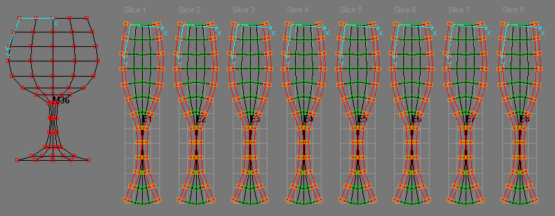
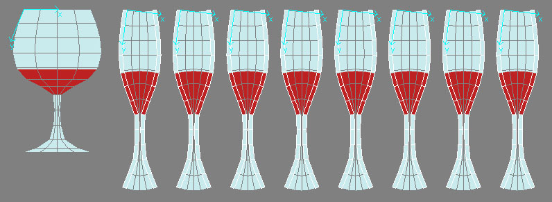
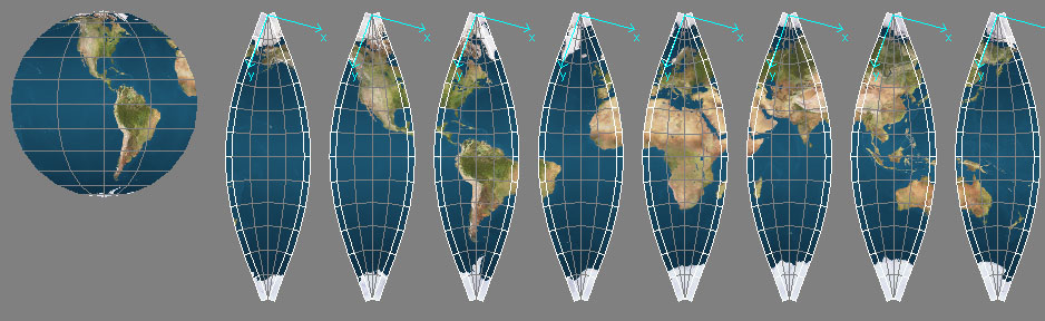
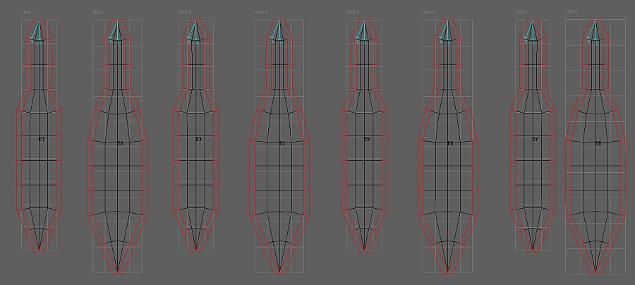
| Elements are the final Step in the Object design chain and represent the flat pattern slices of the three dimensional Object to be produced. Joints for seaming allowances and Textures can be assigned to Elements - finally Elements can be high resolution rendered. | ||
|
||
|
|
||
|
|
||
|
|
||
|
|
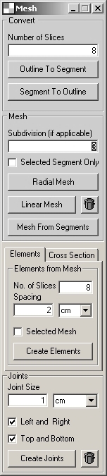
Elements
from Mesh
Number of Slices Spacing Selected Mesh Only Create Elements
Joints Joint Size Left and Right Top and Bottom Create Joints
|
|

|
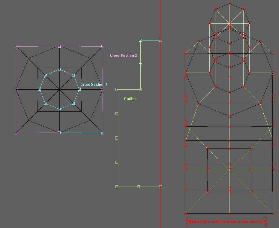
Cross Section
Assign Cross Section:
Note: All cross section segments assigned to the outline segment, must have same number of points
Create Elements Note: the number of elements are given by the nuber od points of the cross section segment assigned to the outline segment. Subdivisions Linear Create Elements |
|
Outline, cross section and mesh example
|
||
|
Elements created from the cross section
modelled mesh
|
||